Aluminium Window Jamb Flashing: Side Seals, Weep Continuity and Cladding Coordination
MC
Author
2026-11-16
Published
13 min read
Reading time
Aluminium Window Jamb Flashing: Side Seals, Weep Continuity and Cladding Coordination
Aluminium windows are not waterproofed by the frame alone. A durable opening depends on a connected drainage and air-sealing arrangement that begins at the head, continues down both jambs, turns through the sill zone, and discharges to the exterior without being blocked by cladding, masonry, sealant, insulation, or debris. Jamb flashing is therefore part of an opening system rather than a decorative strip. It has to work with side seals, sill and head transitions, the wall membrane, the window frame, the selected cladding, the substrate, and the movement expected in the building.
This article is a practical design and site-coordination guide. It uses source labels to distinguish references from site advice. The labels identify the subject area of a source, not a claim that every detail in this article is required by that source. Project drawings, specifications, approvals, manufacturer instructions, and the applicable law remain controlling. Standards and code provisions change, are adopted differently by jurisdiction, and may be subject to project-specific concessions or alternative solutions. Confirm the edition and status that apply before construction.
What jamb flashing is meant to do
Jamb flashing is the vertical part of the opening weather-management system at each side of a window. It may be a proprietary component, a formed sheet, a membrane return, or a combination of compatible layers. Its task is to guide incidental water toward a sill drainage path while preserving the wall’s water-resisting, air-sealing, and sometimes vapour-control functions. The flashing should not be treated as a guarantee against every leak. It is one layer in a system that also relies on correct frame geometry, seals, lap direction, drainage openings, and installation quality.
A jamb detail normally has several interfaces. The window frame must be supported and fixed as specified. A side seal must close the joint without preventing intended drainage. The wall membrane must connect to the opening treatment. The cladding must cover the weathering layers without pinching or puncturing them. The sill must collect water and direct it outward. The head must shed water over the opening and remain compatible with the facade above. If any interface stops the drainage path, water can be redirected into the wall or retained against materials that were not selected for prolonged wetting.
Source label: NCC and ABCB. The National Construction Code and Australian Building Codes Board material provide the regulatory framework for applicable building work in Australia, including provisions concerning weatherproofing, condensation, energy, health, safety, and construction. The precise requirement depends on the building classification, climate, construction type, performance solution, and edition adopted by the relevant authority. This article does not assign a compliance outcome to an unreviewed jamb detail.
Side seals and the two-path principle
A reliable opening detail separates the duties of the seal from the duties of the drainage path. The side seal should limit uncontrolled air and water entry at the frame-to-wall joint, while a separate, intentional route should allow any water that reaches the weathering layer to move down and out. Filling every gap with sealant can create an apparently neat finish while trapping water. Leaving every gap open can allow wind-driven rain and air leakage. The correct result comes from a coordinated primary seal, secondary weathering layer, and drainage outlet.
Use only sealants, tapes, gaskets, backer materials, primers, and membranes that are compatible with the aluminium finish, adjacent coatings, plastics, timber, masonry, and the specified temperature and moisture conditions. Compatibility is not established merely because two products are sold for windows. Check the technical literature and project specification. Observe whether the sealant requires a dry, clean, or primed surface, whether a backing material is needed, and whether the joint is intended to bond on two sides or remain able to move.
A side seal should not bridge an outlet, close a weep, or cross a joint that is intended to accommodate movement. At the same time, a seal that stops before the end of a jamb can leave a direct path behind the trim. The drawing should show where seals terminate, where corners are treated, and how the jamb connects to the sill and head layers. Installers need a detail that can be followed in the field, not only a generic note saying “seal all around.”
Check the frame rebate, drainage slots, pressure-equalised cavities, and manufacturer’s instructions before applying tape or sealant. Do not drill, cut, pack, or seal a frame in a way that changes its drainage design unless the system supplier and project designer approve the change. If a jamb flashing enters a sill pan or sill membrane, the overlap should shed water in the intended direction. Reverse laps, discontinuous corner patches, and adhesive contamination can undermine the whole arrangement.
Sill and head transitions
The sill is normally the collection point. Jamb flashing should meet the sill treatment with a continuous, water-shedding transition. The exact method may be a folded corner, a preformed end dam, a compatible tape, a membrane turn-up, or a proprietary sill component. The design should identify which layer is primary, where its edges terminate, and how water exits to the exterior. Avoid relying on a bead of sealant at a corner as the only connection between vertical and horizontal weathering layers.
Keep the sill drainage route distinct from interior finishes. Packing, insulation, mortar droppings, render, adhesive, and expanding foam can block a narrow drainage path. A sill detail should be checked before the frame is concealed. The frame should be installed level, plumb, square, and adequately supported in accordance with the system requirements. A distorted frame can compromise gaskets, change drainage falls, create binding, and make a correctly designed flashing appear defective.
The head transition has a different exposure and a different water-shedding role. The head flashing or membrane above the frame should discharge to the outside and connect with the wall’s weather-resisting layer. A head flashing should not be hidden behind a facade in a way that sends water into the jamb cavity. At jamb-head corners, the order of laps matters: upper layers should shed over lower layers, and cuts or folds should be sealed only with compatible methods that do not obstruct drainage.
Source label: AS 2047. AS 2047 concerns windows and external glazed doors in buildings and includes performance and test-related requirements for products within its scope. A product’s test or classification does not automatically prove that the installed wall opening, jamb flashing, cladding, or sealant arrangement is compliant. Verify the product scope, installation instructions, project exposure, and interface details separately.
Weep continuity and discharge
Weep continuity means more than having a hole somewhere near the bottom of a wall. Water must have a connected route from the weathering layer to a visible or otherwise effective exterior discharge point. The route can be interrupted by a frame flange, a sill support, a cladding carrier, a cavity barrier, mortar, insulation, sealant, tape, or a membrane that turns the wrong way. Draw the path with a pencil on the detail and follow it around both jambs and the sill. If the line stops, the site detail needs clarification before it is closed.
Weep openings must remain open, clean, and positioned as designed. Do not pack them with sealant or cover them with a trim that has no equivalent outlet. Do not assume that a cavity behind masonry will drain freely if mortar has been allowed to form a bridge. For drained and ventilated cladding, check the cavity closure, flashing outlet, insect screen, and lower termination as one assembly. A screen may be necessary, but it must not become a water plug.
Weep continuity should be considered during every later trade operation. A bricklayer may leave mortar at a flashing edge. A render contractor may coat a drainage slot. A carpenter may push a packer into a membrane return. A facade installer may fix a rail through a concealed flashing without sealing the penetration. A window installer may apply foam across a sill outlet. Coordination responsibility should be assigned, and the inspection hold point should occur before the work is hidden.
A weep is not intended to ventilate an internal room, and it should not be connected to an unplanned internal cavity. It is part of the external water-management strategy. Where a system uses pressure equalisation, baffles, or compartmentation, follow the system design rather than creating additional openings. Uncontrolled holes can increase air leakage, reduce fire or smoke separation, and defeat the intended pressure behaviour.
Cladding coordination
Different claddings place different demands on the jamb detail. Metal sheet cladding may require a cavity, folded trims, thermal movement allowances, and careful treatment of screw penetrations. Fibre-cement or composite boards may use expressed joints, sealant joints, or drained cavities. Timber cladding can move with moisture and needs clearances and ventilation consistent with its installation guidance. Masonry veneer requires attention to cavity drainage, mortar control, flashing support, and the relationship between the window frame and the masonry opening.
For a drained cavity, keep the jamb flashing aligned with the drainage plane rather than burying it behind an unrelated trim. The cladding return should protect the joint from direct exposure while leaving the intended drainage and ventilation route available. If the cladding relies on a face seal, the sealant joint must still be designed for movement, adhesion, backing, and replacement. A face seal should not be used to conceal a missing sill or jamb weathering layer.
At a cladding corner, verify that the finished cover does not reduce the frame clearance needed for movement or maintenance. Confirm the location of fasteners before they are installed. A fixing that punctures a jamb flashing may be acceptable only if the specified system includes a tested or detailed treatment for that penetration. Random field-applied sealant is not a substitute for a documented penetration detail.
Where two claddings meet at a window, identify which one is the upper shedding layer and which one is the lower receiving layer. Provide a clear termination so water cannot run behind the lower cladding. Coordinate trims with the window frame, not just with the nominal opening. Finished dimensions should allow for substrate irregularity, membrane thickness, sealant joints, and movement. Avoid inventing a clearance on site; use the approved detail and supplier instructions.
Masonry, timber, and membrane interfaces
Masonry openings often contain tolerances and construction residue that are more severe than the nominal drawing suggests. Before installing the window, remove loose mortar, check the bearing surfaces, and confirm that the opening is within the permitted installation tolerance. A membrane return may need a clean, dry, sound substrate. Porous masonry may require a compatible primer or a different fixing and sealing method. Do not apply a membrane or tape to a dusty surface and assume that later pressure will restore adhesion.
Timber substrates can shrink, swell, twist, and split. Their moisture condition, grain direction, treatment, coating, and fixing locations affect the opening detail. A sealant joint that works on a stable mineral surface may fail when bonded to moving or contaminated timber. Keep the jamb weathering layer continuous over joints, and provide movement accommodation where the design calls for it. Protect exposed timber while the facade remains incomplete; temporary wetting can change the fit of the frame and the bond of later seals.
Wall membranes need a deliberate relationship with the window. The external water-resistive layer, air barrier, vapour-control layer, insulation layer, and internal lining may not all be in the same plane. A detail that joins only the external membrane can still leak air or create condensation risk if the air-control layer is left discontinuous. Conversely, a tape selected for air sealing may not be suitable as an external drainage flashing. Label the function of each layer and do not use one product for several functions without evidence that it is suitable for all of them.
Membrane laps should be arranged so water travels over, not behind, the lower layer. Protect exposed membranes from ultraviolet exposure and site damage for the period stated by the product literature. Repair punctures with the approved compatible material and method. A patch should extend over sound membrane and be pressed or rolled as required by the product instructions. Do not cover a failed bond with insulation or plasterboard and treat concealment as repair.
Movement and substrates
Aluminium, glass, masonry, timber, membranes, and cladding do not respond identically to temperature, moisture, loading, and building movement. An opening detail must allow the window to remain supported without transferring damaging loads from the wall or facade into the frame. Movement joints in masonry, control joints in render, board joints, and structural deflection zones should be shown relative to the opening. A rigid seal across a movement joint can tear, debond, or pull a flashing out of position.
Consider movement in three directions and at corners. A vertical jamb may move relative to the head flashing. A sill may deflect under load. A cladding panel may expand across a joint while the aluminium frame remains comparatively stable. The installation detail should identify flexible seals, compressible materials, sliding fixings, or separation layers where required. Do not substitute expanding foam for a designed movement joint. Foam can fill irregular voids, but it is not automatically an external weather seal, structural support, vapour control layer, or firestop.
Substrates must be strong enough for the selected fixings and stable enough for the seal. If the opening has lightweight framing, steel framing, concrete, masonry, or a proprietary panel system, use the approved fixing pattern and interface method. Check for services, embedded reinforcement, and edges before drilling. Packers should be durable, correctly placed, and compatible with the frame and seal. Never remove a required support to make room for a flashing or trim without redesigning the support arrangement.
Sequencing and trade coordination
A useful sequence starts with a pre-installation review. Confirm the approved window schedule, frame type, opening size, sill and head details, flashing products, membrane products, sealants, cladding build-up, and inspection points. Resolve conflicts between architectural, structural, facade, waterproofing, fire, and services drawings before work begins. Mark the drainage plane and air-sealing plane on the opening detail so each trade understands which layer it is protecting.
Prepare the opening and substrate first. Install the sill collection and drainage components in the specified order. Fit jamb and head weathering layers so their laps shed outward. Install the frame with the required support, fixings, and tolerances. Connect the frame seals to the wall air and water layers. Complete the cladding and external seals without covering outlets. Finally, complete internal reveals and finishes only after the external inspection has passed.
Site conditions can require a different order, particularly where a window is installed before the surrounding membrane or cladding. If the sequence changes, provide temporary weather protection and document how continuity will be restored. Temporary tape is not necessarily a permanent flashing. A temporary cover should not be left in place if it is incompatible with the final membrane, traps moisture, or prevents inspection.
Use one coordinated shop detail for each materially different opening condition. Typical differences include head versus sill, masonry versus framed wall, recessed versus flush frame, corner window, sillless opening, parapet, balcony edge, and a junction with a movement joint. Generic “typical” details often fail at the exceptions. Record approved substitutions, product batch information where required, photographs before concealment, and any nonconformance and repair.
Inspection and testing boundaries
Inspect before the jamb is hidden. Confirm that the opening is clean; the flashing is continuous; laps face outward; corners are closed as detailed; seals are compatible and continuous; frame drainage slots remain open; fixings do not damage concealed weathering; and the cladding termination preserves the discharge path. Check both jambs, not just the most accessible side. Check the underside of the sill and the top of the head where later work can conceal defects.
Where the project specification calls for water testing, use the nominated method and acceptance criteria. A site hose test may reveal an obvious defect, but it is not automatically equivalent to a laboratory test or a compliance test under a product standard. Record the location, test conditions, duration, result, and corrective action. Do not describe a passed informal observation as a certification, rating, or guarantee.
Source label: AS 1288. AS 1288 addresses the selection and installation of glass in buildings. It is relevant to glazing safety and installation considerations, but it does not by itself design a jamb flashing or prove the weatherproofing of a complete wall opening. Check glass selection, human impact locations, edge clearances, supports, and installation requirements under the applicable edition and project documents.
Source label: AS 4666. AS 4666 is relevant to the inspection and maintenance context for fire and smoke door assemblies and associated fire safety management. It is not a general window-waterproofing standard. If a window or adjacent opening forms part of a fire, smoke, or radiant-heat separation, obtain the specific fire engineering, tested system, penetration, and maintenance requirements. Do not borrow a fire-door requirement and present it as a jamb flashing requirement.
Australian and New Zealand source boundaries
Source label: NCC/ABCB condensation and weather provisions. The applicable NCC provisions may address weatherproofing, condensation management, energy efficiency, fire safety, and building health. Their application depends on the project and the adopted edition. Use the NCC and ABCB explanatory material to identify the governing pathway, then check the complete wall and opening design. A product brochure or a photograph of a similar window is not evidence of NCC compliance.
Source label: New Zealand MBIE guidance and Acceptable Solutions. New Zealand projects may use MBIE building code guidance, including the external moisture pathway associated with E2 Acceptable Solutions and related guidance, as applicable to the building and consent documents. BRANZ guidance and the window, cladding, and membrane manufacturer’s instructions can help explain drained cavities, flashings, junctions, and sequencing. The correct New Zealand document depends on the work, location, construction system, and current consent pathway. Do not use Australian code text as a substitute for New Zealand requirements or assume that a New Zealand detail is approved for an Australian project.
These source labels define factual boundaries. They do not state that a particular flashing profile, sealant bead, cavity arrangement, or fixing pattern is universally required. Obtain the current source, check its scope, and have the responsible designer or building professional resolve conflicts. Where a performance solution is proposed, retain the evidence and conditions that support it.
Handover and maintenance
Handover should include the approved opening details, product data, installation instructions, sealant and membrane information, inspection records, test records, repairs, photographs before concealment, and maintenance advice. Mark the location of concealed drainage routes where future trades might otherwise drill or seal them. Explain that repainting, rendering, recladding, solar attachments, insect screens, security devices, and replacement glazing can affect weeps and seals.
Maintenance should include visual checks for blocked weeps, cracked or debonded sealant, damaged trims, corrosion, movement, staining, failed gaskets, and changes to the adjacent cladding. Keep drainage openings clear using a method that does not damage the frame or membrane. Do not use aggressive tools or solvents without confirming compatibility. If water enters the interior, investigate the whole opening and wall path rather than adding sealant to the first visible gap.
Sealants and membranes have service lives influenced by exposure, movement, substrate preparation, and compatibility. A maintenance recommendation should identify what to observe and when to seek specialist review, but it should not promise a fixed service life unless the responsible product or design documentation supports that statement. The same caution applies to claims about acoustic, thermal, fire, or water performance.
Frequently asked questions
Can sealant alone replace jamb flashing?
No. Sealant can contribute to an air or water seal, but it does not automatically provide a continuous, inspectable drainage path. A sealant joint can debond, crack, be punctured, or trap water. Use the approved opening detail, including the flashing, membrane, frame drainage, and external termination.
Should the jamb flashing be sealed at the bottom?
Only in the manner shown by the approved system. Closing every bottom edge can block drainage, while leaving an unintended gap can expose the wall. The sill and jamb corner should direct water outward and maintain the specified outlet. Follow the product and project detail rather than applying a universal rule.
Can expanding foam be used as the side seal?
Not automatically. Foam may be specified as a gap-filling or insulating material, but it is not inherently a durable external weather seal, structural support, firestop, or membrane connection. Check the frame supplier’s instructions and the project specification for the required air, water, thermal, movement, and fire functions.
What is the most common cause of blocked weeps?
Common causes include mortar droppings, render, sealant, adhesive, insulation, poorly fitted screens, and later fixings. The exact cause must be confirmed on site. Inspect the complete route from the jamb and sill weathering layer to the external outlet before concealment and again after facade work.
Does AS 2047 prove that the installed window is waterproof?
No. AS 2047 concerns windows and external glazed doors within its scope, including product performance and testing matters. Installation in a particular wall, with particular flashing, cladding, substrate, and exposure, must still follow the approved detail and applicable project requirements.
Is AS 1288 a flashing standard?
No. AS 1288 addresses the selection and installation of glass in buildings. It is important to glazing safety and installation, but it does not replace the weatherproofing design for jambs, sills, heads, membranes, or cladding.
When does AS 4666 matter to a window opening?
It matters when the work involves the fire and smoke door maintenance and inspection context covered by that standard, or when the project documents connect an opening to a fire safety system. It is not a general aluminium window flashing standard. Obtain the specific fire system requirements where fire or smoke separation is involved.
Can an Australian detail be used in New Zealand?
Not without review. Australian and New Zealand code pathways, acceptable solutions, product approvals, climate assumptions, and construction practices can differ. Use the current MBIE, BRANZ, consent, designer, and manufacturer information applicable to the New Zealand project.
Conclusion
Good aluminium window jamb flashing is a continuity exercise. The side seals, jamb layers, sill collector, head transition, frame drainage, wall membranes, cladding, masonry or timber substrate, and final weeps must operate as one coordinated system. Draw the water path, identify the air-control path, allow for movement, protect each substrate, sequence the trades, inspect before concealment, and record the finished work. Use NCC/ABCB, AS 2047, AS 1288, AS 4666, and relevant New Zealand guidance within their proper scopes, and confirm current editions and project-specific requirements. Where a detail is uncertain, stop before closing the opening and obtain a documented decision from the responsible designer or system supplier.
Copyright © 2026 添先生. All rights reserved.
Related Articles
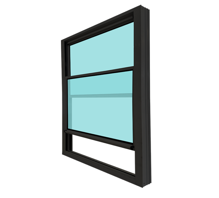
Energy-Efficient Aluminium Double Hung Windows in Northern Territory
Double hung windows offer a timeless design with modern functionality, making them a popular choice…
NCC 2025 External Glazing and Condensation: A Practical Window Guide for Australian Homes
Few things spoil a cold Australian morning quite like the glass of a bedroom window…

You Have Been Looking for Aluminum Windows and Doors Manufacturers
Finding the right aluminum windows and doors manufacturer can be a game-changer for your construction…